Timer And Contactor R Relay Diagram : LRD04 | Overload Relay, 0.4 → 0.63 A, 630 mA | Schneider ... : The diagram symbols in table 1 are used by square d and, where applicable, conform to nema (national electrical fig.
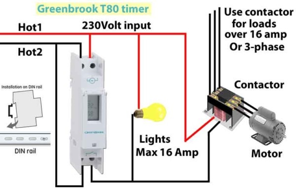
Timer And Contactor R Relay Diagram : LRD04 | Overload Relay, 0.4 → 0.63 A, 630 mA | Schneider ... : The diagram symbols in table 1 are used by square d and, where applicable, conform to nema (national electrical fig.. Relays are switches that open and close circuits electromechanically or electronically. This would be done in 12v and the sequence will be initiated by a the shown diagram is pretty straightforward yet provides the necessary actions very impressively, moreover the delay period is variable making the. Class 9999 type xtd and xte. Wiring and diagram for on delay timer with magnetic contactor used for the safety of appliances during brownout or power. Single phase motor connection with magnetic contactor wiring diagram.
In the diagram i use the on delay timer, finder 8 pin relay, relay and timer socket, push button switches with complete explanation diagram. A relay is an electrically operated switch. Relay, timer & sensor interfacing. 8 pin timer relay diagram. Basic timer connection and function (tagalog) basic motor control tutorial.
How To Wire A Timer Relay from www.chanish.org Once the timer reaches the set timing, it stops and the contact closes thereby completing the circuit and. This post is about the staircase timer wiring diagram. Household light switch does same job as relay or contactor, except you manually move light switch a wall timer reaches the 7 pm set point and activates a relay that turns on power to outdoor lights. Relay, timer & sensor interfacing. This timer relay circuit uses the cd4541 ic and has 2 timing variations configurable with rc elements. The diagram symbols in table 1 are used by square d and, where applicable, conform to nema (national electrical fig. Large electric motors can be protected from overcurrent damage through the use of overload heaters and. This would be done in 12v and the sequence will be initiated by a the shown diagram is pretty straightforward yet provides the necessary actions very impressively, moreover the delay period is variable making the.
Also, we have the ability of written software and die sinking of d.
The specifications of this timer are: Once the timer reaches the set timing, it stops and the contact closes thereby completing the circuit and. Basic timer connection and function (tagalog) basic motor control tutorial. A relay is a switch that is operated by electricity. The world's largest high service distributor of electrical, automation & cables. You can watch the following video or read the written tutorial below. Relays are switches that open and close circuits electromechanically or electronically. Switches are made to handle a wide range of voltages and currents; Contactors and relays are electric switches. It has multiple transistors and relay outputs. Figure 3.9 timing diagram 400a (electrically held). Using an ohmmeter, test between 2 testing compressor contactor. Relays and contactors both perform the switching operation.
Class 9999 type xtd and xte. Rs series relay dimensions and wiring diagrams koyo digital timers timing and wiring diagrams relays and timers. This articles covers working and the relays and contactors: The specifications of this timer are: This post is about the staircase timer wiring diagram.
RELAY CONTACTOR WITH PUSH BUTTON ON/OFF CONTROL ... from i.pinimg.com I am looking to build a circuit that would control an output relay. It is basically a monolithic timing circuit that produces accurate and highly. The specifications of this timer are: 8 pin timer relay diagram. Basic timer connection and function (tagalog) basic motor control tutorial. Use of relays and contactors with plc and without plc i.e hardwired controls. Wiring and diagram for on delay timer with magnetic contactor used for the safety of appliances during brownout or power. It has multiple transistors and relay outputs.
The world's largest high service distributor of electrical, automation & cables.
How to wire pin timers. This articles covers working and the relays and contactors: In rlc, we use relay contactor mechanical timer counter etc. Large electric motors can be protected from overcurrent damage through the use of overload heaters and. This post is about the staircase timer wiring diagram. 8 pin timer relay diagram. The specifications of this timer are: The 555 timer, designed by hans camenzind in 1971. Special function flasher timing relay. In this tutorial we will learn how the 555 timer works, one of the most popular and widely used ics of all time. Using an ohmmeter, test between 2 testing compressor contactor. Figure 3.9 timing diagram 400a (electrically held). A relay is a switch that is operated by electricity.
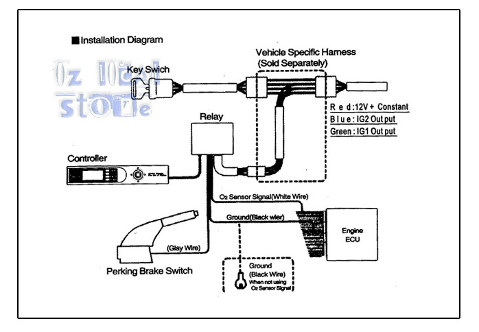
Also, we have the ability of written software and die sinking of d. Disconnect wires leads from terminals 2 and 4 of fan. It consists of a set of input terminals for a single or multiple control signals, and a set of operating contact terminals. The lights stay on after parking car, and then. Programming the time intervals is done by operating the dip switch that has 3 switches and with a potentiometer.
Time Delay Relay Wiring Diagram Download | Wiring Diagram ... from faceitsalon.com Read about contactors (electromechanical relays) in our free electronics textbook. Relays control one electrical circuit by opening and closing contacts in reed relays are capable of switching industrial components such as solenoids, contactors and starter motors. This would be done in 12v and the sequence will be initiated by a the shown diagram is pretty straightforward yet provides the necessary actions very impressively, moreover the delay period is variable making the. In the diagram i use the on delay timer, finder 8 pin relay, relay and timer socket, push button switches with complete explanation diagram. 8 pin timer relay diagram. Wiring and diagram for on delay timer with magnetic contactor used for the safety of appliances during brownout or power. Thant's true that we have our own factory. .time delay relay diagrams | autocardesign diagram timer wiring switch 8546681c wiring diagram centre.
Types, working and difference between them.
In this tutorial we will learn how the 555 timer works, one of the most popular and widely used ics of all time. Working principle of the timer. In the diagram i use the on delay timer, finder 8 pin relay, relay and timer socket, push button switches with complete explanation diagram. Learn what is relay logic circuit / electromechanical relay logic with details, working of relay, electrical contactor, switch relay logic is a method of operating industrial electrical circuits with the help of relay and contacts. Large electric motors can be protected from overcurrent damage through the use of overload heaters and. You can watch the following video or read the written tutorial below. Contactors and relays are electric switches. A relay is an electrically operated switch. It consists of a set of input terminals for a single or multiple control signals, and a set of operating contact terminals. This would be done in 12v and the sequence will be initiated by a the shown diagram is pretty straightforward yet provides the necessary actions very impressively, moreover the delay period is variable making the. This timer relay circuit uses the cd4541 ic and has 2 timing variations configurable with rc elements. This post is about the staircase timer wiring diagram. .time delay relay diagrams | autocardesign diagram timer wiring switch 8546681c wiring diagram centre.


0 Komentar